Spherical Harmonics
Table Of Content
Irradiance Maps
The Rendering Equation as a Convolution
Spherical harmonics
Convolution in Frequency domain
Putting all together
Examples:
Irradiance map and Spherical Harmonics
Calculation of ambient light on a surface requires to calculate the integral of the incoming light, with respect to the whole atmosphere, for each point on the surface. Calculation of the integral on real time is just not possible, however it is possible to precalculate that integral and store it, somehow, to be able to use that information at runtime. There are several ways to precalculate and store the results of the integral, among them we find irradiance maps and spherical harmonics. The irradiance map is an image that stores the result of the integral for "every possible" direction on the atmosphere. The Spherical Harmonics is a technique that allows to approximate an irradiance map with just a few coefficients in a polynomial, thus serving as a way to compress its information, and even to accelerate its calculation.

Irradiance Maps
How do you normally calculate an irradiance map?
Irradiance can be calculated by integrating throught the whole atmosphere the light that comes to a certain point (of the surface we are shading), weighting each ray of light by the cosine of the angle between the normal of the surface and the direction of that ray.
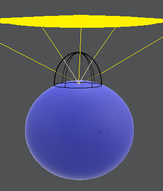
If you take a look at Equation$~\ref{IrradianceEq}$, you can find something familiar. Yes, it looks like a convolution. A convolution of the function of the energy, coming to the point that you are shading, with a kernel that represents the cosine of the angle.
As with any convolution, calculating it by brute-force is really expensive, but calculations in the frequency domain will accelerate it.
As always, Fourier transform is the favorite option for image processing guys when working in frequencies, but we can notice that because of the nature of the phenomena we try to approximate, working in spherical coordinates is a better fit... Aha! Spherical Harmonics to the rescue. By transforming our functions to the frequency domain and working in this domain we can achieve even realtime rates.
Are few frequencies enough for a good approximation?
Here is where the magic happens. The frequency representation of the cosine of the angle that multiplies the incoming energy requires only a few frequencies to be represented, as the higher frequencies of its representation are zero or very small numbers. You could use as few as 4 coefficients to get some nice light or 9 coefficients to make it richer in detail. We can see that this is the case on the pixels of the irradiance map, which change slowly in intensity and color.
The Rendering Equation as a Convolution
The Rendering Equation $\ref{RenderingEquation}$ can be seen as a convolution (Equation $\ref{convolution}$), where $x(\tau)$ is $L_i(w)$ and $s(t-\tau) = \overline{(N \cdot w)}$ is the kernel used in the convolution.
\begin{equation} \int \, L_i(w) \, \overline{(N \cdot w)} \, dw \label{RenderingEquation} \end{equation} \begin{equation} \int_{-\infty }^{\infty} x(\tau) s(t-\tau) d\tau \label{convolution} \end{equation}If we interpret this convolution, for any point in the surface of an object, the incoming light is the sum (integral) of any ray of incoming light weighted by the cosine of its angle with the normal. This is a simple convolution.
Spherical harmonics
Spherical Harmonics (SH) allow to transform any signal to the frequency domain in Spherical Coordinates, as Fourier does in cartesian coordiantes.
In signal processing, it is well known that a convolution in the time domain is equal to a multiplication in the frequency domain (that is why convolutions become so cheap in this domain). This is always used to accelerate operations in image processing.
In order to use this property to accelerate the calculations of the rendering equation, we will need the transformation of $L_i(w)$ and $\overline{(N \cdot w)}$ to the frequency domain, after that we will multiplying the resultant coefficients and transform those coefficients back to the spatial/temporal domain (For spherical harmonics, the convolution in frequencies is not a simple multiplication as it is in Fourier, but the formula is still very simple, we will see later.)
Transforming a Signal to the Frequency domain using Spherical Harmonics.
The transformation of a signal from the temporal/spatial domain to the SH domain is done through the Equation$~\ref{transformation}$, were $f(w)$ is your original function, $Y_l^m$ is the SH basis and $F_l^m$ is the coeficient of the transformation for that SH Basis.
\begin{equation} F_l^m = \int f(w) \, Y_l^m (w) \, ds \label{transformation} \end{equation}
The only thing we don't know from that equation is the SH Basis $Y_l^m$. It turns out there is a formula for those,
\begin{equation} Y_l^m (\theta,\phi) = K_l^m \, e^{im\phi} \, P_l^{|m|} cos(\theta) \label{SHBasisEquation} \end{equation}
with $K_l^m$ a normalization factor and $P_l^{|m|}$ the Legendre polynomials. It is important to notice that in Equation$~\ref{transformation}$, $Y_l^m$ argument is w, while in Equation$~\ref{SHBasisEquation}$ I use $(\theta,\phi)$. This is because I am defining $Y_l^m$ in spherical coordinates, but the transformation for graphics are usually done in the cartesian coordiante system, therefore $ w = (x,y,z) = (sin(\theta) * cos(\phi), sin(\theta) * sin(\phi), cos(\theta))$.
You can get more information from [0].
Equation$~\ref{SHBasisEquation}$ is for the complex representation. In computer graphics we work only with the real part, and to be honest we precalculate those basis once and use them everywhere. In the next table, I am providing the precalculated basis in spherical and in cartesian coordinates. We used the cartesian coordinates, by the way.
| Band $~$ | Base $~$ | Spherical $~$ | Cartesian $~$ |
|---|---|---|---|
| 0 | $Y_0^0$ | $\sqrt{\frac{1}{4\pi}}$ | $\sqrt{\frac{1}{4\pi}}$ |
| 1 | $Y_1^{-1}$ | $\sqrt{\frac{3}{4\pi}} sin\phi sin\theta$ | $\sqrt{\frac{3}{4\pi}} y$ |
| 1 | $Y_1^{0}$ | $\sqrt{\frac{3}{4\pi}} cos\theta$ | $\sqrt{\frac{3}{4\pi}} z$ |
| 1 | $Y_1^{1}$ | $\sqrt{\frac{3}{4\pi}} cos\phi sin\theta$ | $\sqrt{\frac{3}{4\pi}} x$ |
| 2 | $Y_2^{-2}$ | $\sqrt{\frac{15}{4\pi}} sin\phi cos\phi sin^2\theta$ | $\sqrt{\frac{15}{4\pi}} xy$ |
| 2 | $Y_2^{-1}$ | $\sqrt{\frac{15}{4\pi}} sin\phi sin\theta cos\theta$ | $\sqrt{\frac{15}{4\pi}} yz$ |
| 2 | $Y_2^{0}$ | $\sqrt{\frac{5}{16\pi}} (3cos^2\theta -1)$ | $\sqrt{\frac{5}{16\pi}} (3z^2 - 1)$ |
| 2 | $Y_2^{1}$ | $\sqrt{\frac{15}{4\pi}} cos\phi sin\theta cos\theta$ | $\sqrt{\frac{15}{4\pi}} xz$ |
| 2 | $Y_2^{2}$ | $\sqrt{\frac{15}{16\pi}} (cos^2\phi - sin^2 \phi ) sin^2 \theta$ | $\sqrt{\frac{15}{16\pi}} (x^2 - y^2)$ |
You will notice that each Basis belongs to something called Band, and that each Band has certain number of Basis in increasing order. I personally see each band as an indicative of the frequency I am working with and each Basis in the Band as the Axis I am projecting my function onto. For example, Band zero is the frequency zero $Cos (0*2*\pi*t)$, this frequency is constant and it turns out to be the average of the whole function $f(w)$ multiplied by a normalization factor that comes from the Basis.
Once you calculate your coefficients $F_l^m$, you can get back to the original function by applying the inverse transformation (Equation$~\ref{inversetransformation}$).
\begin{equation} f(w) = \int F_l^m \, Y_l^m (w) \, ds \label{inversetransformation} \end{equation}
As with any other transformation to the frequency domain, the more frequencies we use, the better the approximation is to the original function. That being said, let me add that in computer graphics we cheat all the time, so we don't use a very good approximation, we actually use very few frequencies so that the processing time and memory consumption is low. So, don't be surprised when you see this.
Convolution in Frequency domain.
As we said previously, the convolution in frequencies is a multiplication. The equation for Spherical harmonics convolution when the kernel has axial symetry is:
\begin{equation} (h \ast f)_l^m = \sqrt{\frac{4\pi}{2l+1}} h_l^0 F_l^m, \label{convolutionEquation} \end{equation}
where $h$ is the kernel, and $f$ is the function to apply the kernel on.
You can see the derivation in [1]:
Putting all together
In short, the convolution we see in the rendering equation can be performed in the following way:
- Calculate SH transformation of the light $L_i(w)$
- Calculate SH transformation of the clampled cosine $\overline{(N \cdot w)}$
- Perform the convolution with Equation$~\ref{convolutionEquation}$
- Apply inverse transformation to the previous result
The coefficients for the cosine kernel never change. Therefore, we can calculate them once and use them everywhere. In the following table, I provide those coeffients which include also the multiplication by the squared root in Equation$~\ref{convolutionEquation}$; this means that we just need to multiply them with the coefficients of the SH light and apply the inverse transform to get the result of the lighting equation.
| Band $~$ | $~$Value |
| $h_0$ | $\pi$ |
| $h_1$ | $\frac{2\pi}{3}$ |
| $h_2$ | $\frac{\pi}{4}$ |
| $h_3$ | $0$ |
\begin{equation} 2\pi \frac{(-1)^{\frac{l}{2} - 1 }}{(l+2) (l-1)} \left[ \frac{l!}{2^l(\frac{l}{2}!)^2} \right] \label{evenElements} \end{equation}
Examples:
typedef Vec SHB;		//Vec is a class containing a vector of 9 doubles

SHB GetBase(const Vec3f& direction) {
	float x = direction.val[0];
	float y = direction.val[1];
	float z = direction.val[2];
	return SHB(
		1,
		y,
		z,
		x,
		x*y,
		y*z,
		(3 * z*z - 1.0f),
		x*z,
		(x*x - y*y)
		);
}

double function(double theta, double phi)
{
	//you can use any function you want, or even an image as in the next functions
	//return Max(0, 5.0*cos(theta) - 4.0) + Max(0, -4.0 * sin(theta - pi) * cos(phi - 2.5) - 3.0);
	return Min(Max(theta, 0.0), 1.0);;
}

template< double(*Func)(double, double)>
void SphericalHarmonicsTransformation(SHB& RB, int rows, int cols)
{
	double hf = pi / rows;
	double wf = (2.0f * pi) / cols;
	for (int j = 0; j < rows; ++j)
	{
		double phi = hf * double(j);
		double  sinPhi = sin(phi);

		for (int i = 0; i < cols; ++i)
		{
			double theta = wf * double(i);
			// Here, I am using the normal spherical coordinates formulas, however, in the shader the normal is used like normal.xzy changing the place of z and y to make sense of the data
			Vec3f dir(cos(theta)*sin(phi), sin(theta)*sin(phi), cos(phi));
			SHB base = GetBase(dir);
			double value = Func(theta, phi);

			base *= sinPhi;
			RB += base*value;

		}
	}

	SHB coefficients(
		0.282095f	 * hf * wf,
		-0.488603f	 * hf * wf,
		0.488603f	 * hf * wf,
		-0.488603f	 * hf * wf,
		1.092548f	 * hf * wf,
		-1.092548f	 * hf * wf,
		0.315392f	 * hf * wf,
		-1.092548f	 * hf * wf,
		0.546274f	 * hf * wf
		);

	RB = RB.mul(coefficients);

}
General code to calculate an irradiance map using SH to accelerate the transformation
/*
Takes an image and calculates the Coefficients for the ambient light.
Those coefficients contain the convolution with the cosine.
*/
void SphericalHarmonicsOptimized(Mat_ &im, SHB& RB, SHB& GB, SHB& BB)
{
	double area = 0.0f;
	float hf = pi / im.rows;
	float wf = (2.0f * pi) / im.cols;
	for (int j = 0; j < im.rows; ++j)
	{

		float phi = hf * float(j);
		float  sinPhi = sin(phi) * hf * wf;

		for (int i = 0; i < im.cols; ++i)
		{
			float theta = wf * float(i);

			// Here, I am using the normal spherical coordinates formulas, however, in the shader the normal is used like normal.xzy changing the place of z and y to make sense of the data
			Vec3f dir(cos(theta)*sin(phi), sin(theta)*sin(phi), cos(phi));

			SHB base = GetBase2(dir);
			Vec3f color =  im.at(j, i);

			base *= sinPhi;
			area += sinPhi;
			RB += base*color.val[0];
			GB += base*color.val[1];
			BB += base*color.val[2];

		}
	}

	float normalizationFactor = 1.0;

	 SHB coefficients(
		0.282095f * 3.141593f * normalizationFactor,		//factores multiplicados por pi
		-0.488603f * 2.094395f * normalizationFactor,
		0.488603f * 2.094395f * normalizationFactor,
		-0.488603f * 2.094395f * normalizationFactor,
		1.092548f * 0.785398f * normalizationFactor,
		-1.092548f * 0.785398f * normalizationFactor,
		0.315392f * 0.785398f * normalizationFactor,
		-1.092548f * 0.785398f * normalizationFactor,
		0.546274f * 0.785398f * normalizationFactor
		) ;

	 RB = RB.mul(coefficients) ;
	 GB = GB.mul(coefficients);
	 BB = BB.mul(coefficients);

}

/*
Applies the inverse transformation to the coefficients and save them in an irradiance map
*/
void InverseSphericalHarmonics(Mat_ &result, const SHB& RB, const SHB& GB, const SHB& BB)
{
	float hf = pi / result.rows;
	float wf = (2.0f * pi) / result.cols;
	for (int j = 0; j < result.rows; ++j)
	{
		float phi = hf * float(j);

		for (int i = 0; i < result.cols; ++i)
		{
			float theta = wf * float(i);

			Vec3f dir(cos(theta)*sin(phi), sin(theta)*sin(phi), cos(phi));
			SHB base = GetBase(dir);

			base.mul(BaseCoeff);

			Vec3f reslt;

			reslt.val[0] = Max((float)base.ddot(RB), 0.0f);
			reslt.val[1] = Max((float)base.ddot(GB), 0.0f);
			reslt.val[2] = Max((float)base.ddot(BB), 0.0f);

			result.at(j, i) = reslt;		//transform to radiance to be used directly in my engine
		}
	}
}
Displaying an irradiance map from SH coefficients. The default values for the coefficients are used to lit the previous scene.
References
- Wojciech Jarosz, Efficient Monte Carlo Methods for Light Transport in Scattering Media, 2008.
- Kazhdan Michael, FFTs in Graphics and Vision, 2015.
- Ravi Ramamoorthi, Pat Hanrahan, An Efficient Representation for Irradiance Environment Maps, 2001.
- Kazhdan Michael, FFTs in Graphics and Vision, 2015.